DIM
1 ранг
- Регистрация
- 13 Дек 2019
- Сообщения
- 2,291
- Реакции
- 617
- Репутация
- 58
- Город
- Санкт-Петербург
Усилитель Loftin White UX-224 UX-245 UX-280
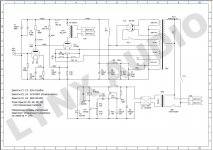
This Amplifier can be considered as the Granddaddy of all Monkeys on a Stick, Loftin White/Morrison 2A3 et al. My original schematic comes from an 1930 Electrad Amplifier, however the design by that time was already quite common and can be traced a good few years further back. It’s main attraction was that it dispensed with the need for a coupling device (transformer, capacitor) between driver- and output-stage, a problem as much then as it is now. I have redrawn and slightly simplified the schematic for clarity, so as to be easily used in this exercise.

As one major war and one generation plus a bit after the original amplifier was designed the stereophonic record was introduced, it was considered sensible to calculate the amplifier as stereo unit. The result should be a set of equations and background information that will allow anyone to calculate their own DC coupled Loftin White Amplifier, using whatever output triodes and driver tetrodes or pentodes are desired to be used (and can be made to work well). As I have recently acquired several pairs of 45’s (including some Globes), as well as some 24’s and one 80 I will use these valves for this example. A wide range of other Valves could be used without any fundamental changes to the basic procedure. I will not again in detail cover the “why” of pentodes as drivers in SE Amplifiers, for that please refer to my article in the newsletter issue 39.
Before we actually start calculating the Values of the components shown, I’ll briefly explain the function of the circuit. The Output Valve (V2) is loaded by the usual Output Transformer and biased by a combination of the input valve and the resistor chain in the cathode of V2. The resistor chain is calculated to provide both the screen grid voltage and the cathode (bias) voltage for the input valve. By supplying the screen grid from cathode of V2 the voltage on the screen grid will vary if the operating point of the output valve varies. Thus a form of negative feedback is introduced for the DC operating point of V2, stabilising the circuit against load and +B voltage changes.
The Anode supply for the input valve is taken from overall +B supply, not from the cathode of V2. If the anode voltage for V1 would be supplied from the cathode of V2 the amplifier would be incapable of attaining it’s full output power, as the current through the input valve anode essentially does not reach 0mA anywhere near the normal operation. Thus the drive to the grid of V2 would fall notably short of reaching 0V grid to cathode voltage, resulting in increased distortion and reduced output power.
The cathode of V1 does not need to be decoupled for AC, the cathode of V2 requires some form of decoupling. By returning the cathode directly to the +B line a shorter current loop is introduced and the value of the decoupling capacitor can be reduced. This so-called “ultrapath” capacitor is C1 and can be used as sole decoupling capacitor. However, if the optional capacitor C3 is fitted it is possible to materially increase the rejection of power line noise, so in a day and age when a 22uF Ansar polypropylene capacitor is quite inexpensive I doubt that there is any justification for omitting this capacitor.
The final “trick” is presented with C2, which at least for the small signal condition allows the use of severely undersized capacitors for C1 (and C3) by providing positive feedback to the anode of V1.
Thus if the audio signal current through V2 is materially modulating the cathode voltage of V2 due to a insufficient size of C1, this modulation is fed straight through to the anode supply of V1 and from there to the anode of V1 and thus the grid of V2. The result is that grid-cathode voltage is retained despite some voltage modulation on the cathode V2 which would normally reduce the grid-cathode modulation leading to reduced output at low frequencies.
Finally, usually the screen grid circuit features it’s own decoupling capacitor. However, in our circuit here the impedance feeding the screen grid is so low (similar to the cathode circuit) that a decoupling capacitor can be omitted with no ill results. There is nothing (other than the low impedance requiring large value capacitors) to stop you from adding such a capacitor from the screen grid to ground, but it is not neccesary, so I’d say make do without.
All in all this circuit is a very neat and professional solution to the problems presented in such an Amplifier and thus comes highly recommended. At first glance it seems very difficult to calculate such a circuit, compared to RC or transformer coupled circuits, but that is not so.
Let us begin the calculations. My RCA Radiotron Manual Issue 10 (RC-10 from here on) suggests a number of operating points for the 45/245 Valve. Living in a power-hungry age we shall take the highest permissible operating condition, shown as follows:
Anode Voltage (really Anode to Cathode): 275 V
Grid Voltage (really Grid to Cathode: -56 V
Amplification Factor (Mu) : 3.5
Anode Current : 36 mA
Load Resistance : 4600 Ohm
Output Power : 2000 milliwatt
Also useful to know are the various capacitance’s between the electrodes of the Valve. The major one is the grid-anode capacitance with 8pf, we also need to account for the grid-heater capacitance, which is 5pf.

From the above we can start to calculate the requirements for the +B voltage and driver stage voltages. We need to add the grid voltage to the anode voltage, this will give us the voltage from the grid of V2 to the Anode of V2. This is effectively “stacked on top of the drivers anode voltage, so the full requirement of the +B Voltage for our amplifier is:
Anode Voltage V2 + (-Grid Voltage V2) + Anode Voltage V1
We have the first two terms but the third term eludes us from the specifications. In order to calculate the necessary anode voltage for our driver tetrode or pentode we need to understand how the tetrode/pentode works. As long as the anode voltage is larger than the screen grid voltage the tetrode/pentode behaves as near ideal (and linear) voltage controlled current source. If the anode voltage drops below the screen grid voltage the classic tetrode kink becomes visible for tetrodes; pentodes materially increase their screen grid current draw. Both conditions leading to substantially increased nonlinearity.
Thus the anode voltage or our valve must not swing below the screen grid voltage for full peak signal supplied to the grid of V2. This is commonly equal to the Bias voltage. So the Anode voltage under quiescent conditions must be at least 56V above the screen grid Voltage. In the interest of improved linearity even the region near the screen grid voltage should be avoided, so if we increase the anode voltage to 10V plus the bias voltage of V2 we should be safely outside any nonlinear operation of our voltage amplifying tetrode or pentode for normal operation. With most tetrodes and pentodes the screen grid voltage can be chosen quite freely, however excessively low screen Voltage will reduce the transconductance of our driver valve and prejudice linearity.
The RC-10 suggest as little as 25V screen grid Voltage for the 24, for our example we shall however use a screen grid voltage of 60V. We now have 60V screen grid voltage, 66V screen grid to anode voltage and thus an anode voltage of V1 of around 126V. Looking at the datasheet and the maximum suggested anode current of 4mA at 250V Anode Voltage it seems reasonable to use around 3mA Anode current. Hopefully this is sufficient to drive the output valve V2 without slewrate limiting, we’ll check later in detail, for now I’m happy as I know the slewrate limit current for a driver stage to drive a 45 is around 1mA, safely below our chosen anode current.
We now can calculate our required +B voltage and current:
Anode Voltage V2 + (-Grid Voltage V2) + Anode Voltage V1
275V + (- (-56V)) + 126V = 457V
The cathode voltage of V2 BTW becomes:
Anode Voltage V2 + (-Grid Voltage V2)
(- (-56V)) + 126V = 182V
To this 457V +B Voltage we need to add a any output transformer losses caused by the non zero DCR of the output transformer winding. If we assume a 200 ohm DCR primary winding and 36mA we have an extra around 7V drop, so we require around 465V of +B. With a stereo amplifier drawing around 36mA per chanal plus 3mA for the driver stage anode current. Thus the current is 78mA. Looking quickly at the charts for the 280 Rectifier in the RC-10 suggests a choke input supply with a 550V – 0 – 550V mains transformer.
We can take a closer look using Duncan Amplifications Power Supply Designer (PSUD from here on). The 80/280 is electrically compatible with the 5Y3 (but has a different socket), something useful to know if you don’t fancy programming your own rectifier models for PSUD. The circuit was simulated according to the screenshot below. It assumes the use of two Maplin power supply chokes (one in each leg of the supply input) as input chokes, a further Maplin Choke as Filter Choke and a small “tuning capacitor” on the input of the Supply to fine tune the +B level in circuit.
So, we have our +B resolved, know the screen voltage for V1 60V), the anode voltage for V1 (126V) and the cathode voltage for V2 (182V). We also know all currents apart from the screen grid current. The RC-10 suggests < 1/3 of the Anode current, so it will not be more than 1mA, looking closely at the curves in the RC-10 it seems it will usually be even less that this, at our static operating point I would estimate < 0.5mA screen grid current.
Ideally we would know exactly also the grid bias voltage for V1, but the charts in the RC-10 only show 90V screen grid voltage. Comparing a few similar tetrodes would suggest a bias voltage for the control grid of around 1V to 1.5V for 60V screen grid voltage. If we base our calculations on 1.5V bias voltage for V1 we can place a modest value adjustable resistor in parallel with R1 and adjust it to make all operating points “fit”.
So now we have:
VC(V1) : 1.5 V
VG2(V1) : 61.5 V
VA(V1) : 127.5 V
VC(V2) : 183.5 V
IA(V1) : 3 mA
IG2(V1) : 0.5 mA
IC(V2) : 36 mA
With the above we can calculate our resistor chain as follows:
R1 = VC(V1) / (IA(V1) + IC(V2))
R2 = (VG2(V1) - VC(V1)) / (IC(V2) - IG2(V1))
R3 = (VC(V2) - VG2(V1)) / (IC(V2))
Filling in our values we get:
R1 = 1.5V / (36mA + 3mA) = 38.46 Ohm
We use 43 Ohm as the nearest standard value and then one number up and parallel a 1k 10 turn adjustable resistor in parallel to fine adjust the operating point.
R2 = (61.5V – 1.5V) / (36mA – 0.5mA) = 1690Ohm
We use 1k5 as nearest standard value available with a substantial power rating (we should use at least 5W audio grade types) and an 180 Ohm 2W resistor in series, making our value 1680 Ohm – I’d say close enough for government work and Pentium users.
R3 = (183.5V – 61.5V) / 36 mA = 3389 Ohm We use 3k3 as nearest standard value available with a substantial power rating (we should use at least 10W audio grade types) and a 91 Ohm 2W resistor in series, making our value 3391 Ohm again close enough.
Now to calculate the minimum value for our anode load resistor. From the Datasheet we know that the transconductance is around 1000 micromhos, a particularly unintuitive measure – I prefer the European notation that calls this 1 milliSiemens, or 1mA/V denoting that a 1V change on the grid gives a 1mA change in current. As we expect our bias to be near 1V we may assume that our maximum grid swing should be less than this. With a 1V peak grid swing we obtain a peak current swing of around 1mA. This should give at least 56V change in grid voltage for our V2, requiring a 56 kOhm anode load resistor for V1. To be on the safe side of that equation I think giving us around 50% leeway is a good idea, so our anode load resistor R4 shall be selected as 75kOhm. The dissipated power is below 1W, so selecting a 2W type here is fine.
The effective anode impedance of V2 is around 400k Ohm, so R4 dominates the output impedance of the driver stage, if we want to be precise it will be around 75k in parallel with 400k or 63kOhm.
With 3mA anode current a voltage of 225V is dropped along this resistor. This adds to our 127.5V anode voltage of V1 to give a voltage of 352.5V on the top end of R4. With our +B at 464V nominal R5 needs to drop the difference between these two voltages with 3mA current, so:
R5 = (464V - 352.5V) / 3mA = 37166 kOhm
I think here we are safe selecting a 33k 2W resistor in series with a 4K3 0.5W Resistor.
With the above we have established all resistors and the DC operating conditions of our Amplifier. We have:
R1 = 43 Ohm in parallel with a 1k 10-Turn trimpot (power uncritical)
R2 = 1k5 Ohm 5W in series with 180 Ohm 2W
R3 = 3k3 Ohm 5W in series with 91 Ohm 2W
R4 = 75k Ohm 2W
R5 = 33k Ohm 2W in series with 4k3 Ohm 0.5W
However, will this kind of operating condition give a reasonable HF response (assuming good transformers) or will the high output impedance of the pentode driver roll off the treble unduly? The effective input capacitance of a 45 is the gridcathode capacitance plus the miller amplified gridanode capacitance. The Miller effect means that the grid-anode capacitance is amplified with approximately the amplification factor (Mu) of the valve. In reality the full Mu does not come into effect in output stages, as there is a quite substantial load which reduces gain, so our calculations assume worst case conditions and hence are rather conservative. Now we get:
CIN(V2) = CGC + (CGA * (Mu+1))
CIN(V2) = 5pF + (8pF * 4.5) = 41pF
If we assume a 75k output impedance of our driver stage we get a time-constant of 75k * 0.041nF = 3uS. On my trusty HP calculator that works out to a –3db point of 53KHz (159000/3 = 53000).
This is not terribly stunning, but sufficient. I can tell a secret now, we don’t specifically have to calculate the slewrate current for a tetrode/pentode driver, as there the output impedance does not vary dramatically from the anode load, so the current sufficient to generate a signal is sufficient to avoid slewing.
This a different story with triode drivers, especially in SRPP where the output impedance of the driver stage can be rather low, while at the same time little current is available from the driver stage.
In such a situation the sides of a high frequency sinewave flatten out (as the signal cannot follow the change in input signal) causing the sinewave to turn into a triangle wave. This causes severe associated intermodulation effects that may fold back into the audio band, especially if a lot of RF junk is floating around.
So to calculate the slewrate current we need to take first the slew rate, which is:
ISL = 2 * PI * f * Vbias * CIN(V2)
We have above determined the –3db frequency as 53KHz and we have CIN(V2) as 33pF and Vbias as 56V. Thus follows:
ISL = 2 * 3.14159 * 53k * 56 * 41pF = 0.76mA
Our current swing is actually +/-1mA, so we swing more current than needed to charge/discharge the input capacitance of our output valve at the highest frequency still being amplified, in reality both the - 3db point and the slewing will be even better, so nothing to worry here.
Just to check the input voltage required to give full output, with 1mA/V transconductance, 75k Anode load and a 56V peak swing for full output we get:
Gain to grid V2 = GM * Rl = 1mA/V * 75k = 75V/V
With this and 56V needed for full power we get 56V / 75V/V = 0.7466V peak input or around 0.53V RMS. Thus our peak input is safely below even the lowest anticipated bias voltage for our input and the input voltage for full output is such that a direct connection to a CD Player should work fine, if a volume control is used on the input of the Amplifier.
Our maximum output will be around 2W RMS for around 5% THD, with 2nd harmonics dominant.
Our last task is to calculate the capacitors C1 to C3.
I think for starters we should set the lower cutoff of the amplifier ahead of the output transformer to 5Hz. This should ensure that the output transformer forms the dominant pole.
For fun, I’ll start to work out C1. C1 is with a current loop that includes the reflected speaker load via the transformer (nominal 4600Ohm) and the anode impedance of V2 (1670 Ohm per RC-10). Together with these impedance C1 should give a –3db point of 5Hz.
This suggests:
C = 1 / ( 2 * PI * f * Z)
Where f is the –3db point and Z is the sum off other impedance’s in the loop at this frequency. Now the impedance is dicey, as the inductance of our output transformer feeds into this, but we cannot really do much here, so using the nominal impedance’s will have to do, it will result in a sufficient value C1.
Thus:
C1 = 1 / (2 * 3.14159 * 5 * (4600+1670)) = 5uF
As a 5uF is not readily available we choose a 4.7uF or 5.6uF Capacitor here. Just to get to the value of C3, this is approximately C1 * Mu, the exact value will have to be selected by trial & error for minimal PSU induced noise. Ideally inject a 300Hz signal into the PSU rail and tune C3 for minimal 300Hz output.
However, based upon our quick and dirty formula we get:
C3 = C1 * Mu
C3 = 4.7uF * 3.5 = 16.45uF
I’d say start with a 15uF unit in place and then tune the value with additional parallel capacitors for minimum noise.
Our last issue is the value of C2. C2 effectively “bootstraps” the anode supply of V1 with the AC voltage on the cathode of V2. So it is effectively a coupling capacitor into this node. The impedance’s present there are the anode impedance of V1 plus the anode load of V1 in parallel with R5. Given the very high value of the first two terms (475k or higher) we find that R5 dominates, so if we calculate for the resistance of R5 and take the next value up we should be fine.
In order to effectively bootstrap the Anode the –3db point here should be 1 Octave lower than for all other calculations; thus follows:
C2 = 1 / (2 * 3.14159 * 2.5 * 37300) = 1.7uF
If we use a 2.2uF Capacitor for C2 we will have no problems.
We now have all components for our Stereo Amplifier using a 24/224 driver and a 45/245 output valve, with an 80/280 rectifier for both channels. I guess a round of shopping is on order.
So here the final list of components:
R1 = 43 Ohm in parallel with a 1k 10-Turn trimpot (power uncritical)
R2 = 1k5 Ohm 5W in series with 180 Ohm 2W
R3 = 3k3 Ohm 5W in series with 91 Ohm 2W
R4 = 75k Ohm 2W
R5 = 33k Ohm 2W in series with 4k3 Ohm 0.5W
C1 = 4.7u F 400V DC
C2 = 2.2u F 630V DC
C1 = 15u F 250V DC plus parallel capacitor to tune PSU noise out
Not shown is the grid leak resistor for V1 – this should be around 100k or a 100k Audio Taper Control may be used to make the Amplifier “integrated”. The use a tetrode in the input stage minimises the input capacitance, so even as high a value attenuator as 100k will cause no problems with the HF response.
Output Transformer – 4600 Ohm to Voice Coil, with most speakers averaging a minimum of ¾ of the rated impedance this should be 4k6 Ohm : 12/6/3 Ohm or 6k Ohm : 16/8/4 Ohm.
The mains transformer needs a 1100V centre tapped winding providing 1100V CT at a load of 110mA, also needed are a 5V 3A winding for the 80. Both 24 and 45 have 2.5V heaters at 1.75A and 1.5A respectively, so three more 2.5V 4A windings complete our list, assuming we use AC heaters on the 45.
For DC heaters a slightly higher voltage is needed and the needed circuit should be simulated including any regulators if used or just be provided with enough headroom voltage and current.
We finally need three Maplin Chokes (nominally 10H/100mA max) and a 630V DC 22uF capacitor plus a 630V DC 47uF capacitor and a suitable chassis. The tuning capacitor (first in the filter chain) needs to be adjusted in circuit under nominal conditions for the correct HT of 464V, the bias of V1 should be adjusted for 127.5V on the Anode of V1 and C3 should be adjusted for lowest noise.
Not shown in the schematic, a capacitor of approximately 0.47uF may be connected across each input choke and (again) tuned for maximum suppression of noise (100Hz to be precise) to reduce noise levels even further. This is called "resonant choke input supply", google it to find out more....
The Hum cancellation scheme suggested by Steve Bench (http://members.aol.com/sbench/humbal.html) may be used to minimise the noise from the cathode emission modulation due to AC heating. Combining all these methods should reduce the hum on the output of the Amp to below 1mV with AC heaters or much lower with DC heaters, giving at least 72db Signal/Noise ratio for AC heaters.
Failing to implement all relevant hum suppression measures may lead to a very poor S/N ratio, so better read up. That should do it and give a very high quality Amplifier, assuming the output transformers are of sufficient quality and inductance. Those that have kept track might have noticed that this Amp can be made entirely without electrolytic capacitors, the preferred approach if you ask me.
Если вы решите построить этот усилитель или рассчитать и сделать свой собственный, помните, что высокое напряжение потенциально смертельно опасно, поэтому соблюдайте соответствующие меры безопасности. Кроме того, пожалуйста, не говорите, что это был просто пример расчета, усилитель не моделировался и не строился, поэтому никаких гарантий правильной работы дать нельзя, хотя, если законы физики и электричества таковы, как я их помню, он ДОЛЖЕН работать нормально.
 www.diyaudio.com
This Amplifier can be considered as the Granddaddy of all Monkeys on a Stick, Loftin White/Morrison 2A3 et al. My original schematic comes from an 1930 Electrad Amplifier, however the design by that time was already quite common and can be traced a good few years further back. It’s main attraction was that it dispensed with the need for a coupling device (transformer, capacitor) between driver- and output-stage, a problem as much then as it is now. I have redrawn and slightly simplified the schematic for clarity, so as to be easily used in this exercise.
As one major war and one generation plus a bit after the original amplifier was designed the stereophonic record was introduced, it was considered sensible to calculate the amplifier as stereo unit. The result should be a set of equations and background information that will allow anyone to calculate their own DC coupled Loftin White Amplifier, using whatever output triodes and driver tetrodes or pentodes are desired to be used (and can be made to work well). As I have recently acquired several pairs of 45’s (including some Globes), as well as some 24’s and one 80 I will use these valves for this example. A wide range of other Valves could be used without any fundamental changes to the basic procedure. I will not again in detail cover the “why” of pentodes as drivers in SE Amplifiers, for that please refer to my article in the newsletter issue 39.
Before we actually start calculating the Values of the components shown, I’ll briefly explain the function of the circuit. The Output Valve (V2) is loaded by the usual Output Transformer and biased by a combination of the input valve and the resistor chain in the cathode of V2. The resistor chain is calculated to provide both the screen grid voltage and the cathode (bias) voltage for the input valve. By supplying the screen grid from cathode of V2 the voltage on the screen grid will vary if the operating point of the output valve varies. Thus a form of negative feedback is introduced for the DC operating point of V2, stabilising the circuit against load and +B voltage changes.
The Anode supply for the input valve is taken from overall +B supply, not from the cathode of V2. If the anode voltage for V1 would be supplied from the cathode of V2 the amplifier would be incapable of attaining it’s full output power, as the current through the input valve anode essentially does not reach 0mA anywhere near the normal operation. Thus the drive to the grid of V2 would fall notably short of reaching 0V grid to cathode voltage, resulting in increased distortion and reduced output power.
The cathode of V1 does not need to be decoupled for AC, the cathode of V2 requires some form of decoupling. By returning the cathode directly to the +B line a shorter current loop is introduced and the value of the decoupling capacitor can be reduced. This so-called “ultrapath” capacitor is C1 and can be used as sole decoupling capacitor. However, if the optional capacitor C3 is fitted it is possible to materially increase the rejection of power line noise, so in a day and age when a 22uF Ansar polypropylene capacitor is quite inexpensive I doubt that there is any justification for omitting this capacitor.
The final “trick” is presented with C2, which at least for the small signal condition allows the use of severely undersized capacitors for C1 (and C3) by providing positive feedback to the anode of V1.
Thus if the audio signal current through V2 is materially modulating the cathode voltage of V2 due to a insufficient size of C1, this modulation is fed straight through to the anode supply of V1 and from there to the anode of V1 and thus the grid of V2. The result is that grid-cathode voltage is retained despite some voltage modulation on the cathode V2 which would normally reduce the grid-cathode modulation leading to reduced output at low frequencies.
Finally, usually the screen grid circuit features it’s own decoupling capacitor. However, in our circuit here the impedance feeding the screen grid is so low (similar to the cathode circuit) that a decoupling capacitor can be omitted with no ill results. There is nothing (other than the low impedance requiring large value capacitors) to stop you from adding such a capacitor from the screen grid to ground, but it is not neccesary, so I’d say make do without.
All in all this circuit is a very neat and professional solution to the problems presented in such an Amplifier and thus comes highly recommended. At first glance it seems very difficult to calculate such a circuit, compared to RC or transformer coupled circuits, but that is not so.
Let us begin the calculations. My RCA Radiotron Manual Issue 10 (RC-10 from here on) suggests a number of operating points for the 45/245 Valve. Living in a power-hungry age we shall take the highest permissible operating condition, shown as follows:
Anode Voltage (really Anode to Cathode): 275 V
Grid Voltage (really Grid to Cathode: -56 V
Amplification Factor (Mu) : 3.5
Anode Current : 36 mA
Load Resistance : 4600 Ohm
Output Power : 2000 milliwatt
Also useful to know are the various capacitance’s between the electrodes of the Valve. The major one is the grid-anode capacitance with 8pf, we also need to account for the grid-heater capacitance, which is 5pf.
From the above we can start to calculate the requirements for the +B voltage and driver stage voltages. We need to add the grid voltage to the anode voltage, this will give us the voltage from the grid of V2 to the Anode of V2. This is effectively “stacked on top of the drivers anode voltage, so the full requirement of the +B Voltage for our amplifier is:
Anode Voltage V2 + (-Grid Voltage V2) + Anode Voltage V1
We have the first two terms but the third term eludes us from the specifications. In order to calculate the necessary anode voltage for our driver tetrode or pentode we need to understand how the tetrode/pentode works. As long as the anode voltage is larger than the screen grid voltage the tetrode/pentode behaves as near ideal (and linear) voltage controlled current source. If the anode voltage drops below the screen grid voltage the classic tetrode kink becomes visible for tetrodes; pentodes materially increase their screen grid current draw. Both conditions leading to substantially increased nonlinearity.
Thus the anode voltage or our valve must not swing below the screen grid voltage for full peak signal supplied to the grid of V2. This is commonly equal to the Bias voltage. So the Anode voltage under quiescent conditions must be at least 56V above the screen grid Voltage. In the interest of improved linearity even the region near the screen grid voltage should be avoided, so if we increase the anode voltage to 10V plus the bias voltage of V2 we should be safely outside any nonlinear operation of our voltage amplifying tetrode or pentode for normal operation. With most tetrodes and pentodes the screen grid voltage can be chosen quite freely, however excessively low screen Voltage will reduce the transconductance of our driver valve and prejudice linearity.
The RC-10 suggest as little as 25V screen grid Voltage for the 24, for our example we shall however use a screen grid voltage of 60V. We now have 60V screen grid voltage, 66V screen grid to anode voltage and thus an anode voltage of V1 of around 126V. Looking at the datasheet and the maximum suggested anode current of 4mA at 250V Anode Voltage it seems reasonable to use around 3mA Anode current. Hopefully this is sufficient to drive the output valve V2 without slewrate limiting, we’ll check later in detail, for now I’m happy as I know the slewrate limit current for a driver stage to drive a 45 is around 1mA, safely below our chosen anode current.
We now can calculate our required +B voltage and current:
Anode Voltage V2 + (-Grid Voltage V2) + Anode Voltage V1
275V + (- (-56V)) + 126V = 457V
The cathode voltage of V2 BTW becomes:
Anode Voltage V2 + (-Grid Voltage V2)
(- (-56V)) + 126V = 182V
To this 457V +B Voltage we need to add a any output transformer losses caused by the non zero DCR of the output transformer winding. If we assume a 200 ohm DCR primary winding and 36mA we have an extra around 7V drop, so we require around 465V of +B. With a stereo amplifier drawing around 36mA per chanal plus 3mA for the driver stage anode current. Thus the current is 78mA. Looking quickly at the charts for the 280 Rectifier in the RC-10 suggests a choke input supply with a 550V – 0 – 550V mains transformer.
We can take a closer look using Duncan Amplifications Power Supply Designer (PSUD from here on). The 80/280 is electrically compatible with the 5Y3 (but has a different socket), something useful to know if you don’t fancy programming your own rectifier models for PSUD. The circuit was simulated according to the screenshot below. It assumes the use of two Maplin power supply chokes (one in each leg of the supply input) as input chokes, a further Maplin Choke as Filter Choke and a small “tuning capacitor” on the input of the Supply to fine tune the +B level in circuit.
So, we have our +B resolved, know the screen voltage for V1 60V), the anode voltage for V1 (126V) and the cathode voltage for V2 (182V). We also know all currents apart from the screen grid current. The RC-10 suggests < 1/3 of the Anode current, so it will not be more than 1mA, looking closely at the curves in the RC-10 it seems it will usually be even less that this, at our static operating point I would estimate < 0.5mA screen grid current.
Ideally we would know exactly also the grid bias voltage for V1, but the charts in the RC-10 only show 90V screen grid voltage. Comparing a few similar tetrodes would suggest a bias voltage for the control grid of around 1V to 1.5V for 60V screen grid voltage. If we base our calculations on 1.5V bias voltage for V1 we can place a modest value adjustable resistor in parallel with R1 and adjust it to make all operating points “fit”.
So now we have:
VC(V1) : 1.5 V
VG2(V1) : 61.5 V
VA(V1) : 127.5 V
VC(V2) : 183.5 V
IA(V1) : 3 mA
IG2(V1) : 0.5 mA
IC(V2) : 36 mA
With the above we can calculate our resistor chain as follows:
R1 = VC(V1) / (IA(V1) + IC(V2))
R2 = (VG2(V1) - VC(V1)) / (IC(V2) - IG2(V1))
R3 = (VC(V2) - VG2(V1)) / (IC(V2))
Filling in our values we get:
R1 = 1.5V / (36mA + 3mA) = 38.46 Ohm
We use 43 Ohm as the nearest standard value and then one number up and parallel a 1k 10 turn adjustable resistor in parallel to fine adjust the operating point.
R2 = (61.5V – 1.5V) / (36mA – 0.5mA) = 1690Ohm
We use 1k5 as nearest standard value available with a substantial power rating (we should use at least 5W audio grade types) and an 180 Ohm 2W resistor in series, making our value 1680 Ohm – I’d say close enough for government work and Pentium users.
R3 = (183.5V – 61.5V) / 36 mA = 3389 Ohm We use 3k3 as nearest standard value available with a substantial power rating (we should use at least 10W audio grade types) and a 91 Ohm 2W resistor in series, making our value 3391 Ohm again close enough.
Now to calculate the minimum value for our anode load resistor. From the Datasheet we know that the transconductance is around 1000 micromhos, a particularly unintuitive measure – I prefer the European notation that calls this 1 milliSiemens, or 1mA/V denoting that a 1V change on the grid gives a 1mA change in current. As we expect our bias to be near 1V we may assume that our maximum grid swing should be less than this. With a 1V peak grid swing we obtain a peak current swing of around 1mA. This should give at least 56V change in grid voltage for our V2, requiring a 56 kOhm anode load resistor for V1. To be on the safe side of that equation I think giving us around 50% leeway is a good idea, so our anode load resistor R4 shall be selected as 75kOhm. The dissipated power is below 1W, so selecting a 2W type here is fine.
The effective anode impedance of V2 is around 400k Ohm, so R4 dominates the output impedance of the driver stage, if we want to be precise it will be around 75k in parallel with 400k or 63kOhm.
With 3mA anode current a voltage of 225V is dropped along this resistor. This adds to our 127.5V anode voltage of V1 to give a voltage of 352.5V on the top end of R4. With our +B at 464V nominal R5 needs to drop the difference between these two voltages with 3mA current, so:
R5 = (464V - 352.5V) / 3mA = 37166 kOhm
I think here we are safe selecting a 33k 2W resistor in series with a 4K3 0.5W Resistor.
With the above we have established all resistors and the DC operating conditions of our Amplifier. We have:
R1 = 43 Ohm in parallel with a 1k 10-Turn trimpot (power uncritical)
R2 = 1k5 Ohm 5W in series with 180 Ohm 2W
R3 = 3k3 Ohm 5W in series with 91 Ohm 2W
R4 = 75k Ohm 2W
R5 = 33k Ohm 2W in series with 4k3 Ohm 0.5W
However, will this kind of operating condition give a reasonable HF response (assuming good transformers) or will the high output impedance of the pentode driver roll off the treble unduly? The effective input capacitance of a 45 is the gridcathode capacitance plus the miller amplified gridanode capacitance. The Miller effect means that the grid-anode capacitance is amplified with approximately the amplification factor (Mu) of the valve. In reality the full Mu does not come into effect in output stages, as there is a quite substantial load which reduces gain, so our calculations assume worst case conditions and hence are rather conservative. Now we get:
CIN(V2) = CGC + (CGA * (Mu+1))
CIN(V2) = 5pF + (8pF * 4.5) = 41pF
If we assume a 75k output impedance of our driver stage we get a time-constant of 75k * 0.041nF = 3uS. On my trusty HP calculator that works out to a –3db point of 53KHz (159000/3 = 53000).
This is not terribly stunning, but sufficient. I can tell a secret now, we don’t specifically have to calculate the slewrate current for a tetrode/pentode driver, as there the output impedance does not vary dramatically from the anode load, so the current sufficient to generate a signal is sufficient to avoid slewing.
This a different story with triode drivers, especially in SRPP where the output impedance of the driver stage can be rather low, while at the same time little current is available from the driver stage.
In such a situation the sides of a high frequency sinewave flatten out (as the signal cannot follow the change in input signal) causing the sinewave to turn into a triangle wave. This causes severe associated intermodulation effects that may fold back into the audio band, especially if a lot of RF junk is floating around.
So to calculate the slewrate current we need to take first the slew rate, which is:
ISL = 2 * PI * f * Vbias * CIN(V2)
We have above determined the –3db frequency as 53KHz and we have CIN(V2) as 33pF and Vbias as 56V. Thus follows:
ISL = 2 * 3.14159 * 53k * 56 * 41pF = 0.76mA
Our current swing is actually +/-1mA, so we swing more current than needed to charge/discharge the input capacitance of our output valve at the highest frequency still being amplified, in reality both the - 3db point and the slewing will be even better, so nothing to worry here.
Just to check the input voltage required to give full output, with 1mA/V transconductance, 75k Anode load and a 56V peak swing for full output we get:
Gain to grid V2 = GM * Rl = 1mA/V * 75k = 75V/V
With this and 56V needed for full power we get 56V / 75V/V = 0.7466V peak input or around 0.53V RMS. Thus our peak input is safely below even the lowest anticipated bias voltage for our input and the input voltage for full output is such that a direct connection to a CD Player should work fine, if a volume control is used on the input of the Amplifier.
Our maximum output will be around 2W RMS for around 5% THD, with 2nd harmonics dominant.
Our last task is to calculate the capacitors C1 to C3.
I think for starters we should set the lower cutoff of the amplifier ahead of the output transformer to 5Hz. This should ensure that the output transformer forms the dominant pole.
For fun, I’ll start to work out C1. C1 is with a current loop that includes the reflected speaker load via the transformer (nominal 4600Ohm) and the anode impedance of V2 (1670 Ohm per RC-10). Together with these impedance C1 should give a –3db point of 5Hz.
This suggests:
C = 1 / ( 2 * PI * f * Z)
Where f is the –3db point and Z is the sum off other impedance’s in the loop at this frequency. Now the impedance is dicey, as the inductance of our output transformer feeds into this, but we cannot really do much here, so using the nominal impedance’s will have to do, it will result in a sufficient value C1.
Thus:
C1 = 1 / (2 * 3.14159 * 5 * (4600+1670)) = 5uF
As a 5uF is not readily available we choose a 4.7uF or 5.6uF Capacitor here. Just to get to the value of C3, this is approximately C1 * Mu, the exact value will have to be selected by trial & error for minimal PSU induced noise. Ideally inject a 300Hz signal into the PSU rail and tune C3 for minimal 300Hz output.
However, based upon our quick and dirty formula we get:
C3 = C1 * Mu
C3 = 4.7uF * 3.5 = 16.45uF
I’d say start with a 15uF unit in place and then tune the value with additional parallel capacitors for minimum noise.
Our last issue is the value of C2. C2 effectively “bootstraps” the anode supply of V1 with the AC voltage on the cathode of V2. So it is effectively a coupling capacitor into this node. The impedance’s present there are the anode impedance of V1 plus the anode load of V1 in parallel with R5. Given the very high value of the first two terms (475k or higher) we find that R5 dominates, so if we calculate for the resistance of R5 and take the next value up we should be fine.
In order to effectively bootstrap the Anode the –3db point here should be 1 Octave lower than for all other calculations; thus follows:
C2 = 1 / (2 * 3.14159 * 2.5 * 37300) = 1.7uF
If we use a 2.2uF Capacitor for C2 we will have no problems.
We now have all components for our Stereo Amplifier using a 24/224 driver and a 45/245 output valve, with an 80/280 rectifier for both channels. I guess a round of shopping is on order.
So here the final list of components:
R1 = 43 Ohm in parallel with a 1k 10-Turn trimpot (power uncritical)
R2 = 1k5 Ohm 5W in series with 180 Ohm 2W
R3 = 3k3 Ohm 5W in series with 91 Ohm 2W
R4 = 75k Ohm 2W
R5 = 33k Ohm 2W in series with 4k3 Ohm 0.5W
C1 = 4.7u F 400V DC
C2 = 2.2u F 630V DC
C1 = 15u F 250V DC plus parallel capacitor to tune PSU noise out
Not shown is the grid leak resistor for V1 – this should be around 100k or a 100k Audio Taper Control may be used to make the Amplifier “integrated”. The use a tetrode in the input stage minimises the input capacitance, so even as high a value attenuator as 100k will cause no problems with the HF response.
Output Transformer – 4600 Ohm to Voice Coil, with most speakers averaging a minimum of ¾ of the rated impedance this should be 4k6 Ohm : 12/6/3 Ohm or 6k Ohm : 16/8/4 Ohm.
The mains transformer needs a 1100V centre tapped winding providing 1100V CT at a load of 110mA, also needed are a 5V 3A winding for the 80. Both 24 and 45 have 2.5V heaters at 1.75A and 1.5A respectively, so three more 2.5V 4A windings complete our list, assuming we use AC heaters on the 45.
For DC heaters a slightly higher voltage is needed and the needed circuit should be simulated including any regulators if used or just be provided with enough headroom voltage and current.
We finally need three Maplin Chokes (nominally 10H/100mA max) and a 630V DC 22uF capacitor plus a 630V DC 47uF capacitor and a suitable chassis. The tuning capacitor (first in the filter chain) needs to be adjusted in circuit under nominal conditions for the correct HT of 464V, the bias of V1 should be adjusted for 127.5V on the Anode of V1 and C3 should be adjusted for lowest noise.
Not shown in the schematic, a capacitor of approximately 0.47uF may be connected across each input choke and (again) tuned for maximum suppression of noise (100Hz to be precise) to reduce noise levels even further. This is called "resonant choke input supply", google it to find out more....
The Hum cancellation scheme suggested by Steve Bench (http://members.aol.com/sbench/humbal.html) may be used to minimise the noise from the cathode emission modulation due to AC heating. Combining all these methods should reduce the hum on the output of the Amp to below 1mV with AC heaters or much lower with DC heaters, giving at least 72db Signal/Noise ratio for AC heaters.
Failing to implement all relevant hum suppression measures may lead to a very poor S/N ratio, so better read up. That should do it and give a very high quality Amplifier, assuming the output transformers are of sufficient quality and inductance. Those that have kept track might have noticed that this Amp can be made entirely without electrolytic capacitors, the preferred approach if you ask me.
Если вы решите построить этот усилитель или рассчитать и сделать свой собственный, помните, что высокое напряжение потенциально смертельно опасно, поэтому соблюдайте соответствующие меры безопасности. Кроме того, пожалуйста, не говорите, что это был просто пример расчета, усилитель не моделировался и не строился, поэтому никаких гарантий правильной работы дать нельзя, хотя, если законы физики и электричества таковы, как я их помню, он ДОЛЖЕН работать нормально.
Calculating DC coupled Single Ended Valve Amplifiers - Part #1
A practical Example - the UX-224 UX-245 UX-280 Stereophonic Loftin White Amplifier First Published in the London Live DIY HiFi Circle Newsletter # 42 http://www.earthcurrents.com/london-live/ This Amplifier can be considered as the Granddaddy of all Monkeys on a Stick, Loftin White/Morrison...
Последнее редактирование модератором:
")